Products & Core Technology
Traditional CAE workflows typically face high computational cost, long turnaround, strong engineering dependence, and demanding talent requirements.
We break these barriers by turning physical simulation into real-time, second-scale feedback.
Why We Stand Out
Our core technology stack includes:
- Multi-architecture neural fusion: We combine CNNs, RNNs, MLPs, graph neural networks, and other complementary architectures in a unified training-and-inference pipeline to build high-fidelity surrogate models on geometric and mesh tensor representations.
- Physics-informed neural networks (PINNs): Our AI is not a naive black box—it respects underlying physical laws.
- AI-first native infrastructure: Built from the ground up on modern deep networks and a distributed inference engine.
End-to-end automated flow
Engineers no longer need to spend weeks tuning mesh reconstruction and boundary conditions:
- Automated extraction: Direct compatibility with and import of data from Ansys, Abaqus, and similar engineering formats.
- AI preprocessing & conversion: Turn complex arbitrary 3D geometries into a unified large-model tensor representation.
- Instant inference: Run state-of-the-art operator-style proxy networks to return stress, thermal, and other 3D physical fields in an instant.
iAISIM Platform Experience
On touch devices, swipe horizontally; on desktop, drag the scrollbar or use the arrow buttons.
UI tour





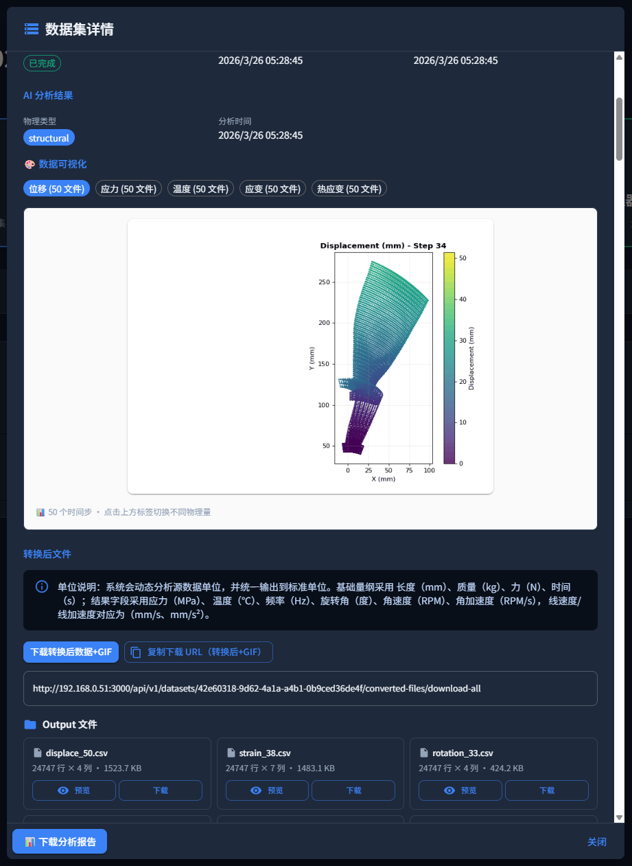
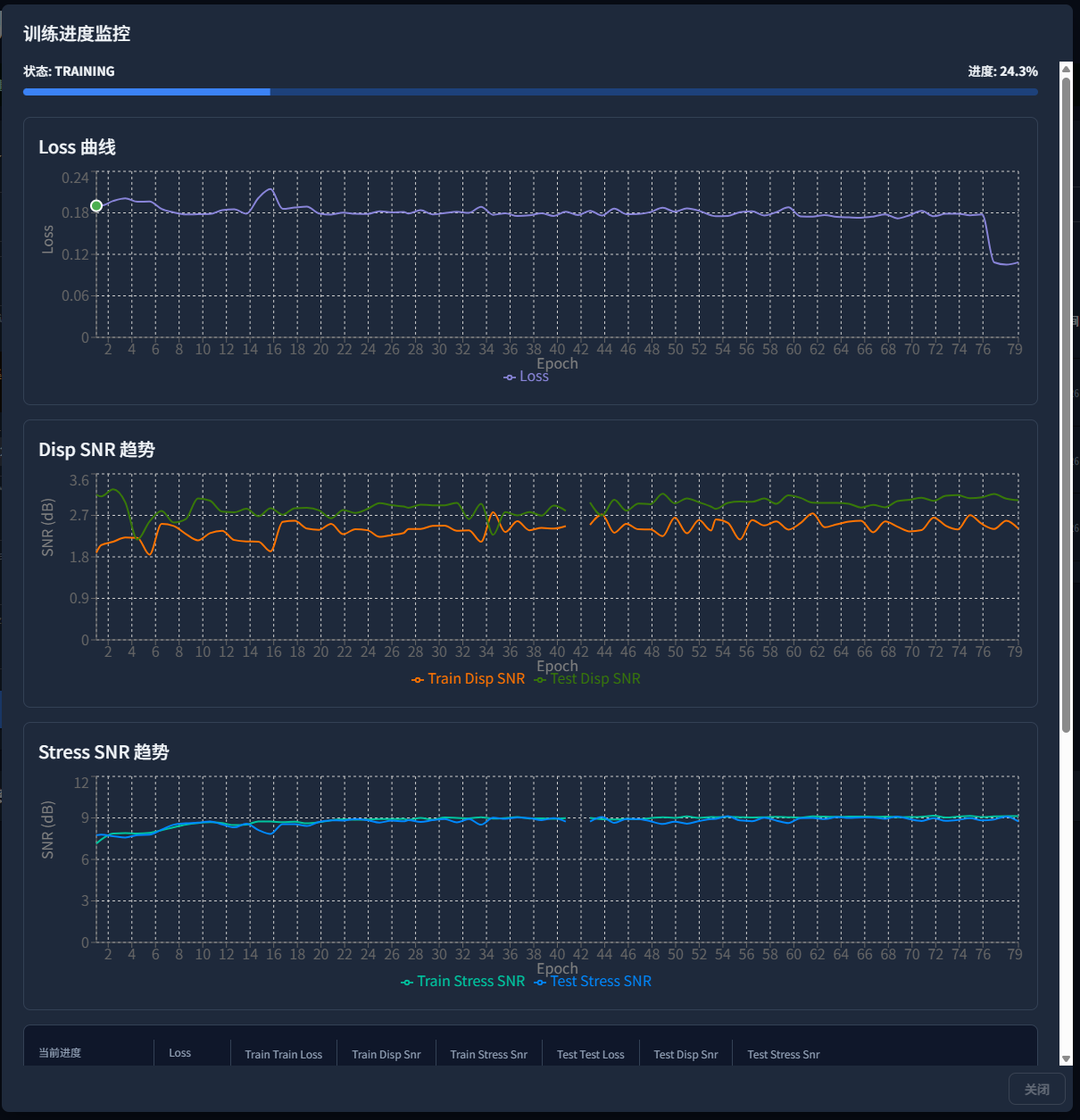
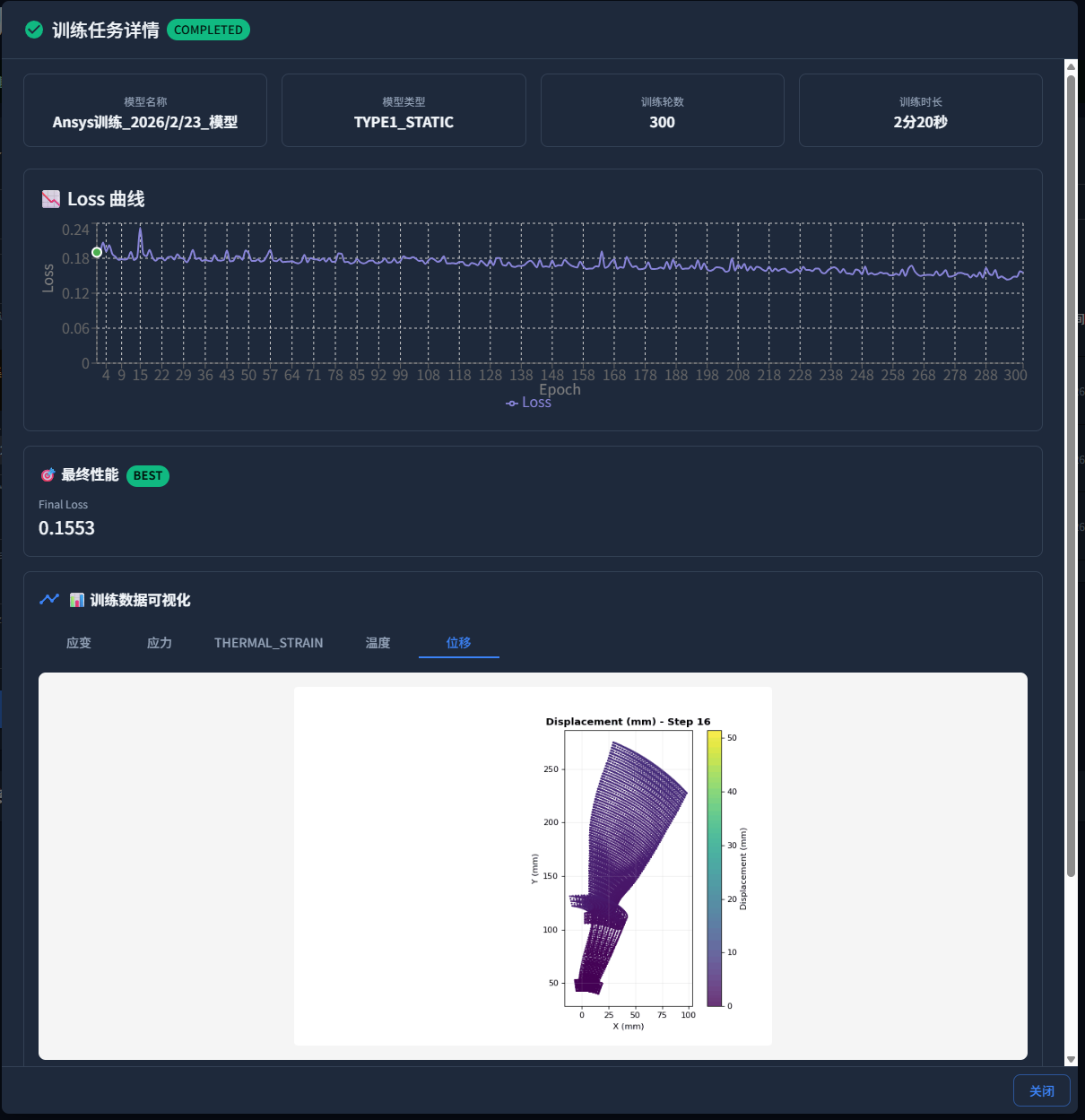
Module demos
Case Studies & Delivered Results
We empower leading companies in aerospace, new energy vehicles, and advanced manufacturing. This page includes public technical validation case studies (excerpts from our materials) and summarizes typical efficiency gains seen in industry deployments.
Technical validation (excerpt)
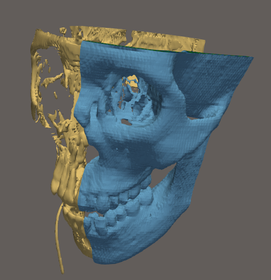
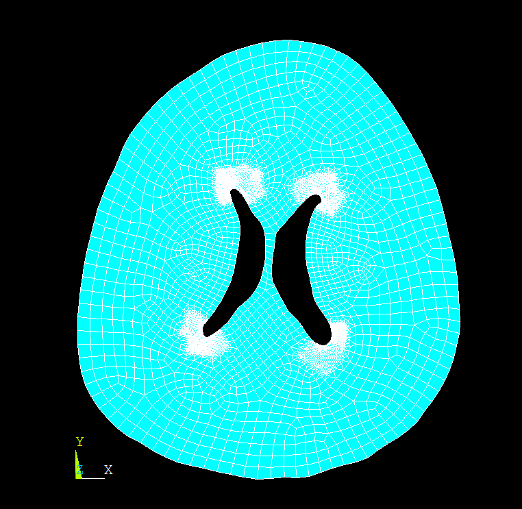
Case 1 — Multiphysics brain tissue: normal pressure hydrocephalus
The model uses a coupled pore-pressure and thermal finite-element formulation to study nonlinear behavior of normal pressure hydrocephalus under structural–thermal coupling. Brain tissue uses hyperelastic constitutive laws; under combined pressure and thermal loading, the coupled elements solve for displacement, pore pressure, and temperature.
The figures and demo videos below are public case materials and match the site’s visual style.
Case 2 — Turbomachinery blades: hot/cold geometry and NASA Rotor 67
In turbomachinery, hot–cold methods are common for rotor blades: the as-manufactured geometry is the cold shape, while the in-service shape under thermal and centrifugal effects is the hot shape. Designers usually iterate from a target hot geometry toward a manufacturable cold geometry.
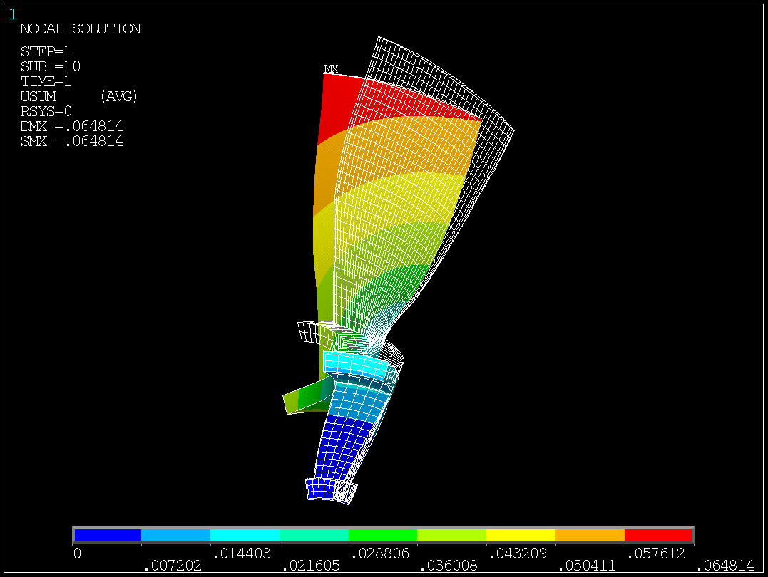
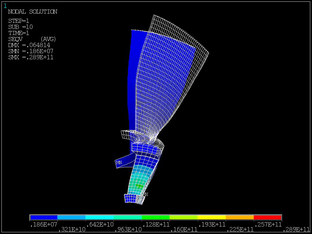
Model and mesh: NASA Rotor 67 fan blade disk sector model, representative of aerospace turbofan compressor subsystems; the sector is meshed with SOLID186 solid elements.
Loads and boundary conditions:
- Centrifugal load from rotation;
- Thermal load from reference vs. operating temperature;
- Unsteady flow pressure on the blade surface;
- Thermal boundary conditions on selected elements, with temperatures from 100°C to 400°C.
The figures and F1 / F2 demos below belong to the same case materials.
Book a Demo
// Submit your preliminary joint-test requirements //